This is my first non-nixie clock. Built using the schematic and code provided by José Pino .

José has provided pre-compiled HEX code suitable for the PIC16F628 (I'm using a PIC16F628A without any problems) Code is also supplied for the PIC16F84. The layout is very simple and keeps good time - gaining only a few seconds after a couple of weeks running. The first photo shows the complete clock (two surface mount capacitors are mounted under the board, as well as the two 10k pull-down resistors from pins 6 & 7).

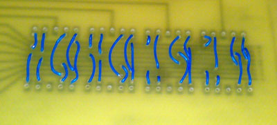
The second photo shows the wire-wrap wire links that sit under the 7-segment displays. The first two displays are mounted with the decimal point at the bottom, the second two with the decimal point at the top - this is done on purpose as when the clock is running the two inner-most decimal points blink to provide a colon separator. Power is provided by a 5v DC wallwart.

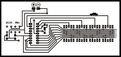
I created a PCB based upon José's schematic. Keeping things neat was a challenge, with the jumpers under the individual displays being the most elegant solution I could come up with. The board was created using the toner transfer method and hand-drilled.
This was a great project and everything worked out well :)
José has some great PIC projects on his site, well worth a look!